An AI CAD drawing generator uses machine learning models, natural language processing and computer vision to convert text prompts, 2D sketches or raster images into vector drawings and 3D geometry. Engineering and design teams use these tools to accelerate early-stage drafting, generate parametric solids, and build baseline assets for computer-aided design software. The speed is real. The governance gap is also real: pulling an automated drafting tool into a formal technical workflow demands risk tiering, an evidence chain, and a validation protocol that someone signs.
Executive Summary for Engineering and Governance Leaders
- What works todaytext-to-CAD and image-to-CAD systems reliably produce concept geometry, editable 2D vector drafts, and simple-to-moderate parametric solids (STEP, CadQuery). Published benchmarks show acceptable performance on basic and intermediate feature sets, with measurable degradation on advanced geometry.
- What does not work todayno browser-based generative model compiles a native, fully constrained
.dwgwith layers, blocks and associative dimensions in seconds. Native DWG almost always requires a conversion or tracing step in AutoCAD or DraftSight. - The critical distinctionB-Rep and NURBS solids (STEP, IGES, CadQuery code) are editable engineering data. Polygonal meshes (STL, OBJ, GLB) are visual approximations without feature history.
- Governance requirementtreat every AI output as a pre-validation draft artifact. Mandatory geometric audit, FEA where the part is load-bearing, and independent sign-off by a certified professional engineer before manufacturing, tooling or construction.
- Procurement requirementverify commercial-use grants in the EULA, zero-data-retention terms, GDPR posture, SOC 2 Type II or ISO 27001 evidence, and export-format parity between free and paid tiers before you allow adoption. Skip this and you invite Shadow AI through the front door.
Who this guide is for, and what it helps you decide
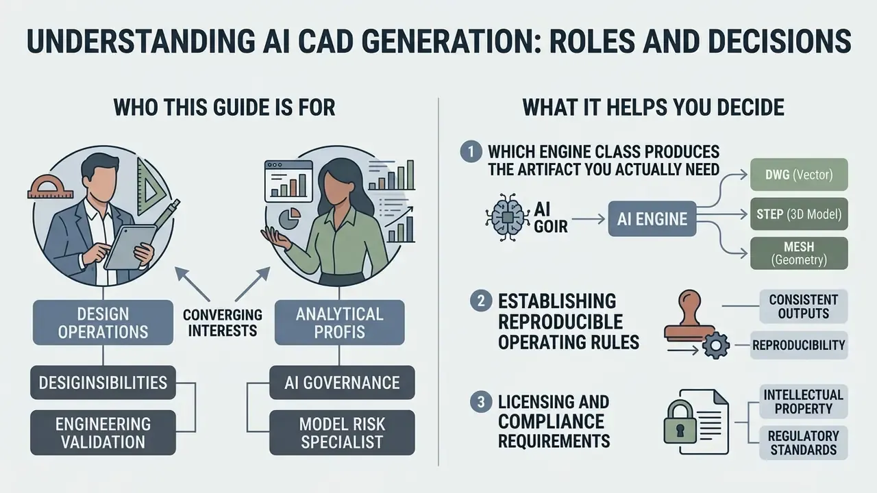
This is written for two readers who rarely sit in the same meeting. The first is the engineering lead who needs faster concept geometry without shipping a defective part. The second is the governance owner (model risk, compliance, security) who has to explain to an auditor how an AI-generated drawing became a drawing of record.
Three decisions sit underneath everything below: which engine class produces the artifact you actually need, which file format preserves engineering intent, and who signs off before geometry becomes metal, concrete or a filed patent figure. Everything else is detail.
If you only take one operating rule from this page, take this one: an output you cannot reproduce is an output you cannot defend.
What an AI CAD Drawing Generator Can Create
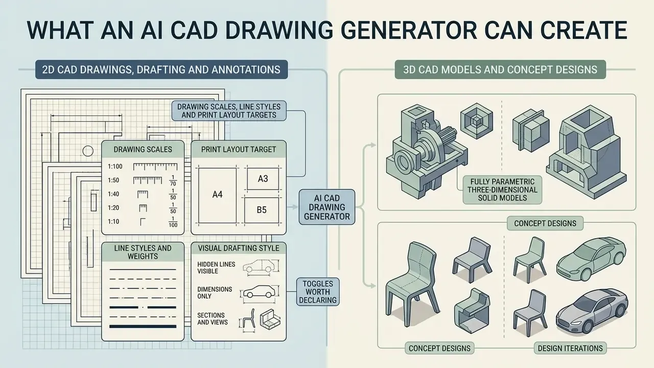
An ai cad drawing generator produces a wide spectrum of engineering outputs, from two-dimensional vector drafting to fully parametric three-dimensional solid models. Modern ai cad drawings differ in their underlying mathematical representation, file structure and editability inside standard CAD software. Those differences decide everything downstream, so it pays to be pedantic about them early.
2D CAD drawings, drafting and annotations
An AI-driven cad drawing engine generates two-dimensional orthographic projections, floor plans, isometric views and exploded assembly diagrams from natural language or reference inputs. These tools reconstruct vector entities (lines, arcs, polylines, hatch patterns) that follow foundational drafting standards such as ISO 128-1:2020 for general execution rules and ISO 129-1:2018 for dimensioning and tolerances.
In automated 2D technical drafting, the system parses input constraints to produce readable layouts with scaled viewport boundaries and associative annotations. According to NASA engineering drawing standards (GP-435 Vol. II Rev. C), every technical sheet requires a declared scale, graphic scales adjacent to the title block, and associative dimensions linked to geometric coordinates. Sheets without a scale must be explicitly labelled "NONE" or "NOT TO SCALE". Systems trained on vector command sequences, such as CAD-Coder (2025), can generate 2D sketches with geometric annotations, though final drafting approval still needs a human check on dimension callouts, layer organisation and line weights.
Drawing scales, line styles and print layout targets
To prepare AI-generated 2D drafts for client review, coordination sets and plotting, specify scale and line-style parameters directly in the prompt. Generative models default to statistically "average" line weights unless you constrain them.
- Drawing scales enforce standard engineering and architectural scales explicitly. Use 1:20 for detail views and joinery sections, 1:50 for interior layouts and furniture plans, 1:100 for building footprints and site coordination, 1:5 or 1:2 for machined feature details.
- Print layout target declare the physical sheet constraint (for example an A3 title-block layout for review prints, or A1 for construction issue) so text height, leader lines and associative dimensions do not overlap during vectorization. A drawing that reads perfectly on screen frequently collapses at A3 print scale if the text-to-geometry ratio was never constrained.
- Line styles and weights request distinct layer mapping following ISO 128 conventions.
Visible Linesat 0.5 mm continuous,Hidden Linesat 0.25 mm dashed,Centerlinesat 0.25 mm chain line,Section Cutat 0.7 mm continuous,Dimensions / Textat 0.18 to 0.25 mm. - Visual drafting style name the target aesthetic.
technical(thin uniform black lines on white),blueprint(white lines on a cyan field), orschematic(symbol-driven, minimal hatching). Each maps to a different training distribution and produces markedly different legibility. - Toggles worth declaring dimension visibility, grid overlay, material hatches, room labels, north arrow. Turning hatches off during early iteration cuts visual noise and makes geometric errors much easier to spot.
3D CAD models and concept designs
A 3D cad model generator converts text or visual prompts into volumetric representations suitable for industrial design, product prototyping and mechanical engineering. Advanced 3D cad systems build parametric feature trees or boundary representations (B-Rep) made of exact NURBS surfaces rather than a visual mesh. That is the line between an ai cad model generator you can machine from and a pretty preview.
Research on generative engineering frameworks shows that foundation models can synthesise complex parametric solids. Text2CAD (Sadil Khan et al., NeurIPS 2024) demonstrates a pipeline that turns 2D sketches into 3D models through extrusion and command sequences across 178,238 designs in the DeepCAD dataset.
«Text2CAD is the first framework for generating parametric CAD models from text using instructions understandable to designers of all skill levels». Text2CAD, Sadil Khan et al., arXiv:2409.17106 (2024). https://arxiv.org/abs/2409.17106
NURBGen (2025) maps textual descriptions directly to Non-Uniform Rational B-Splines parameters across 300,000 models in the partABC dataset.
«NURBGen is the first framework generating high-fidelity 3D CAD models directly from text using NURBS, outperforming Text2CAD and GPT-4o on geometric accuracy». NURBGen, arXiv:2511.06194 (2025). https://arxiv.org/abs/2511.06194
These generated designs let mechanical engineers inspect solid geometry, evaluate physical volume and establish baseline product models before committing to detailed manufacturing workflows. A 2026 empirical study, Foundation Models for Automatic CAD Generation, evaluated foundation models across 97 engineering design problems using a unified generation pipeline for mechanical parts. The finding is encouraging and sobering at once: automated CAD synthesis has moved from demonstration to measurable benchmarking, yet it stays task-specific rather than general-purpose.
| Output Category | Input Modalities | Primary File Formats | Parametric Editability | Target Application |
|---|---|---|---|---|
| 2D CAD Drawings | Text prompts, raster sketches, PDF blueprints | DWG, DXF, SVG, PDF | High (vector entities, layers, associative dimensions) | Architectural floor plans, orthographic drafting, schematics |
| 3D CAD Models | Text descriptions, orthographic views, B-Rep code | STEP, IGES, CadQuery code, B-Rep | High (full feature tree, NURBS surfaces, parametric history) | Mechanical parts, CNC tooling, additive manufacturing |
| Concept Visualizations | Natural language, single-view photos | PNG, WebP, OBJ, GLB | Low (mesh-based or visual raster output) | Early ideation, design reviews, client presentations |
| Patent & Documentation Line Art | Text prompts, exploded assembly references | SVG, PNG, PDF | Low to medium (vector traceable, no constraints) | Patent filings, instruction manuals, service documentation |
Table 1: Comparison of AI-generated 2D CAD drawings, 3D CAD models, concept visualizations and line art by input, output type, editability and use case.
How AI Generates CAD Drawings From Text, Images and Prompts
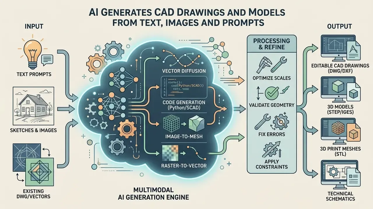
Modern cad ai generator systems rely on multimodal deep learning architectures that translate unstructured language or raw pixels into structured, executable CAD code or vector primitives. Understanding that transformation is what lets a design team write inputs that minimise geometric invalidity instead of gambling on a lucky seed.
Text-to-CAD prompts for drawings and models
Text to cad conversion depends on large language models fine-tuned on procedural modelling scripts (CadQuery, OpenSCAD) and sequential CAD command histories. To generate cad drawings accurately, the system parses the prompt into geometric primitives, spatial relationships, dimensional constraints, and operations such as extrusions, fillets and chamfers.
High-precision prompts follow a hierarchy: global bounding shape, explicit dimensional limits, local feature definitions, workplane setup, stepwise build instructions. Research on Proactive Agents for Robust Text-to-CAD Generation (2026) formalises this into three mandatory sections, General shape, Setup (workplane and origin) and Build description (stepwise operations). PrintPal's AI prompting guides add explicit millimetre units, feature positions and mating clearances. When an ai generate cad drawings request omits dimensions, the model infers scale from its training distribution, and that is the usual root of dimensional drift in complex mechanical assemblies.
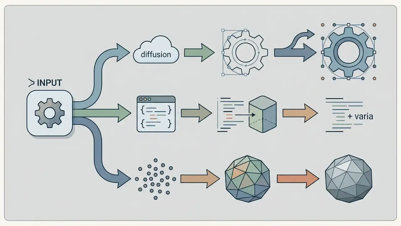
Generation engines are not interchangeable: vector, code and mesh pipelines
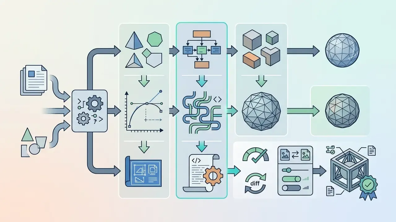
A recurring procurement error is treating all "AI CAD" engines as one category. In practice, four architecturally distinct pipelines are sold under the same label, and each produces a different class of artifact.
Image, sketch and photo input for CAD generation
Image-conditioned CAD generation turns raster photos, hand-drawn sketches or PDF vector sheets into structured geometry. Frameworks such as Img2CAD (CVPR 2025) use Structured Visual Geometry wireframe extraction as an intermediate layer, bridging pixel data and parametric B-Rep reconstruction across datasets like ABC-mono (more than 200,000 rendered CAD pairs).
«Img2CAD is the first approach using 2D images to generate CAD models with editable parameters, introducing the ABC-mono dataset of more than 200,000 CAD models with renderings». Img2CAD, arXiv:2410.03417 (2024). https://arxiv.org/abs/2410.03417
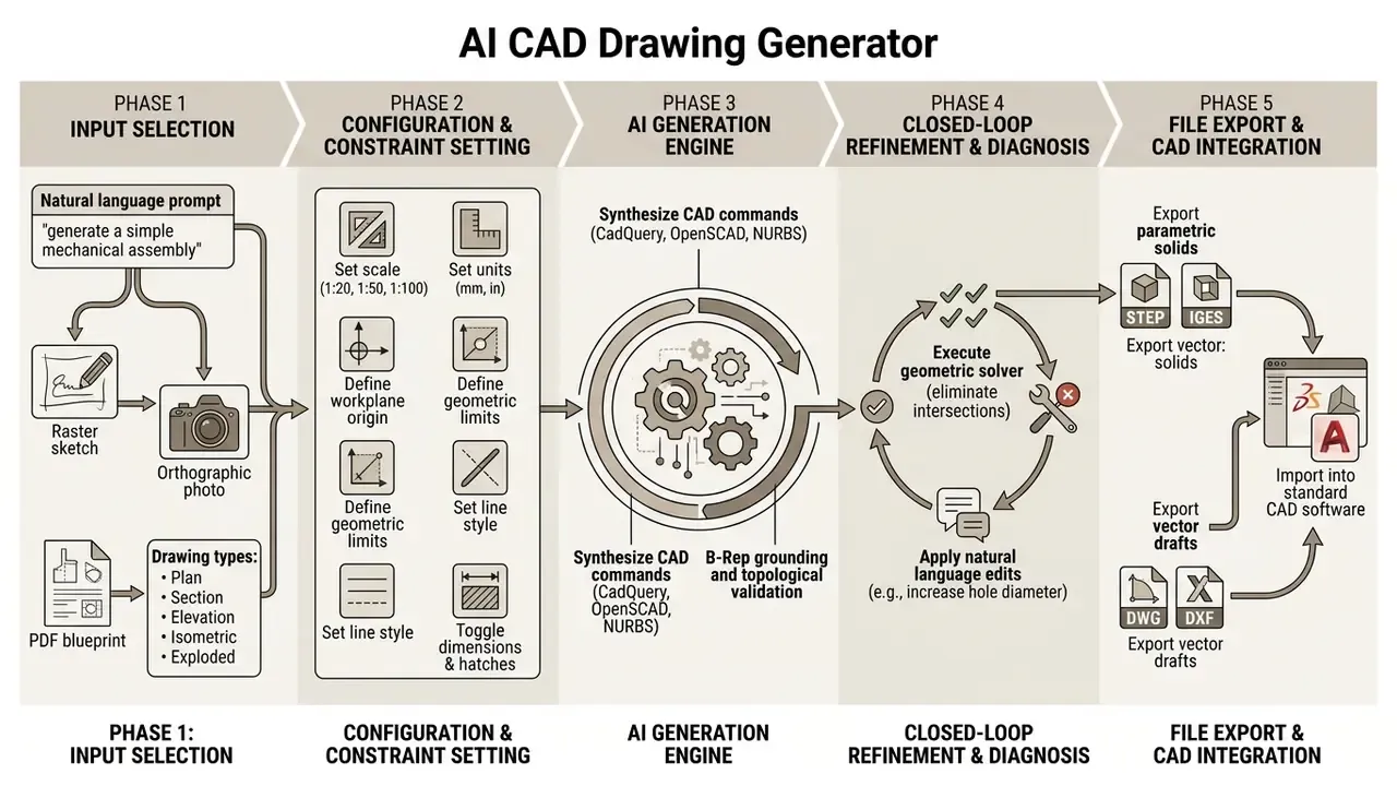
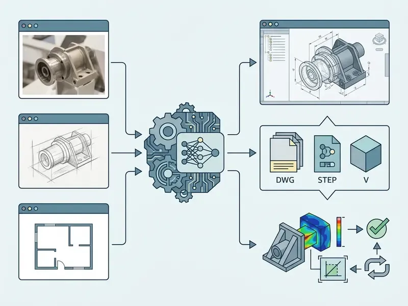
For physical object reconstruction, systems like CADDreamer (2025) process single-view photos through two-stage diffusion pipelines to infer hidden geometry and output watertight solids. CADCrafter (CVPR 2025) targets parametric CAD generation from unconstrained single images. Drawing2CAD (ACM MM 2025) treats vector engineering drawings as input command sequences, learning extrusion and cut operations from orthographic views. Together these tools let engineers convert legacy paper blueprints or napkin sketches into digital CAD assets fast, which matters most in plants where the only surviving drawing is a photocopy from 1987.
Constraints, scale and refinement after generation
Raw outputs from an ai to create cad drawings engine often carry minor geometric defects: unconstrained sketches, self-intersecting surfaces, invalid face selections. Modern platforms implement closed-loop diagnostics to resolve these before export.
Frameworks like PR-CAD (2026) and FutureCAD (2026) introduce progressive refinement and B-Rep grounding transformers. FutureCAD maps natural language commands ("select the top face") directly to topological primitives.
«FutureCAD achieves a median Chamfer Distance of 31.12 and an invalidity ratio of approximately 1.01% on complex parts, substantially outperforming baselines without geometric grounding». FutureCAD, arXiv:2603.11831 (2026). https://arxiv.org/abs/2603.11831
CAD-Refiner (CVPR 2026) uses topological structure graphs as complementary constraints during refinement passes. IterCAD (2026) uses multi-view engineering drawings with persistent dimensional constraints to isolate topological anomalies, so iterative prompt adjustments converge toward industry-standard precision. Iterative Diagnosis-Driven Augmented Generation (MODELSWARD 2025) formalises the same principle as a closed loop combining syntactic, runtime and geometric analysis over exact B-Rep geometry. Same lesson each time: one pass is a draft, not a deliverable.
Common AI generation failure modes and prompt-level fixes
Most dissatisfaction with these tools traces back to three or four reproducible failure classes rather than to model quality. Each has a deterministic prompt-level remedy.
| AI failure symptom | Root cause | Step-by-step prompt fix |
|---|---|---|
| Dimensional drift: features migrate between iterations, holes land off-centre | No declared datum or coordinate origin, so the model re-infers placement each pass | State the datum: "Set origin (0,0,0) at bottom-left corner of the base plate; place hole centre at X=15 mm, Y=20 mm; all dimensions referenced from this datum." |
| Distorted multi-storey architecture (G+3 and above) | Generator overloaded by vertical circulation, programme and envelope context at once | Decompose the task: generate each floor plan separately at fixed footprint dimensions, then request one combined section or elevation referencing the confirmed floor-to-floor height. |
| Self-intersecting or non-manifold geometry | Undefined tolerances, zero-radius internal corners, no manifold requirement | Add manufacturing constraints: "Apply minimum 0.5 mm fillet radii to all interior sharp corners; ensure watertight manifold topology; no coincident or overlapping faces." |
| Wrong scale on import (25.4x error) | Units never declared, model defaults to inches or unitless | Declare units in every prompt and re-declare at export: "All dimensions in millimetres; export STEP in millimetre units." |
| Unreadable annotation at print size | No sheet size or text height constraint | Specify: "Layout for A3 sheet, 1:50 scale, dimension text height 2.5 mm, no overlapping leader lines." |
| Mesh output where a solid was needed | The engine is a mesh generator, not a parametric engine | Change tool class, not prompt: request STEP or CadQuery output from a code-generating or B-Rep engine (see engine comparison above). |
| Ignored prompt, generic result | Prompt written as a wish rather than a specification | Rewrite using the five-block template (role, global geometry, local features, setup and origin, manufacturing constraints) below. |
AI CAD File Formats: DWG, CAD Files and Export Options
File compatibility decides whether an ai dwg generator or an ai cad file generator slots into your enterprise software estate or becomes a dead end. Learn this before you start exporting, not after a supplier rejects the package. Generating a visually convincing CAD rendering is fundamentally different from compiling an exact mathematical solid or a native DWG vector database.
When an AI-generated result is a real editable CAD file
A genuine, fully editable cad file contains precise mathematical entities: B-Rep solids, analytic NURBS surfaces, fully constrained 2D vector primitives, stored inside structured layers and block hierarchies. Polygonal 3D meshes (STL, OBJ, GLB) instead represent objects as flat triangular facets with no curve radius data and no feature history.
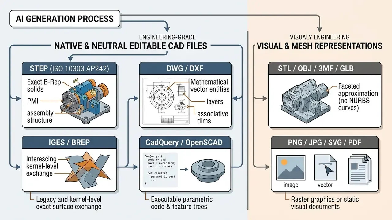
Research across CAD interoperability benchmarks confirms that true editability requires exact B-Rep geometry or executable parametric code. A raster image or a 3D mesh cannot be natively modified inside traditional CAD software without vectorization or re-surfacing, while neutral solid files such as STEP AP242 retain precise boundary definitions, product structure, PMI and configuration data, ready for CNC machining, finite element analysis and mechanical drafting. Note one practical asymmetry: STEP preserves accurate geometry but generally does not preserve the original feature tree, so a "STEP round-trip" hands you a dumb solid unless the vendor also exports native or code-based parameters.
Configuring non-parametric 3D mesh exports (Quad, Raw, polygon count, PBR)
When exporting non-parametric 3D representations from an ai cad maker, apply explicit topology controls. These settings decide whether the asset is usable downstream at all.
- Quad mesh topology (Quad Mode) structures geometry into four-sided polygons. Essential if the asset goes into Blender, Maya or 3ds Max for subdivision-surface modelling, UV work or organic refinement. Quad meshes deform predictably, and they are the only sane choice for further sculpting.
- Triangular mesh (Raw Mode) generates lightweight three-sided facets. Faster to produce, simpler to process, and best suited to immediate rapid prototyping through FDM or SLA slicing engines, which triangulate everything anyway.
- Polygon count management high-poly settings preserve smooth fillets, tight radii and curvature continuity, but inflate file size (frequently above 50 MB) and slow every downstream operation. Low-poly settings prioritise real-time WebGL rendering and quick client review, at the cost of visible faceting and stair-stepping on curved surfaces.
- Material shading protocols choose PBR (Physically Based Rendering) when you need realistic roughness, metalness and normal maps for visualization software. Choose Shaded view for flat, high-contrast colour that exposes geometric errors and surface discontinuities during engineering review. Use All / combined where the same asset serves both audiences.
- Prompt guidance and seed higher guidance values yield more defined, literal geometry; lower values yield looser interpretations. Fixing the seed is what makes a generation reproducible, and reproducibility is non-negotiable in any auditable workflow.
- Watertightness Russian additive-manufacturing standards (GOST R 70242-2022, GOST R 57586-2017) explicitly require closed, watertight surfaces and warn that low STL resolution produces visible triangulation, stair-stepping and surface deviation. Verify mesh closure before slicing, every time.
| Mesh export setting | Recommended for engineering / manufacturing | Recommended for visualization / review |
|---|---|---|
| Mesh mode | Raw / triangular (slicer-ready) | Quad (clean topology for DCC editing) |
| Polygon density | High enough to hold tolerance on radii | Low to medium for fast WebGL preview |
| Material | Shaded (defect visibility) | PBR (roughness and metalness maps) |
| Format | STL, 3MF | GLB, OBJ, FBX |
| Reproducibility | Fixed seed plus logged prompt | Free seed variation acceptable |
What to verify before importing into AutoCAD
When you move files from an autocad ai generator free tier or an enterprise drafting engine into Autodesk AutoCAD, run a structured verification audit. It prevents drafting corruption and scaling failures that otherwise surface at the worst possible moment.
Before importing generated assets into active drawing sets, check five parameters:
- Unit system and scale: confirm whether the file was generated in millimetres, inches or metres. Unscaled imports routinely produce 25.4x dimensional errors.
- Layer architecture: ensure entities sit on designated, standardised layers (
WALLS,DIMS,CENTERLINES) rather than a single collapsed0layer. AutoCAD's PDF import dialog lets you set layer assignment, insertion point, scale and rotation explicitly at import time. Use it. - Dimension association and DIMSCALE: check that linear dimensions match actual model coordinates. Per Autodesk technical documentation, model-space dimensions require
DIMSCALEset to the inverse of the plot scale (a 1/4 plot scale meansDIMSCALE = 4), while paper-space viewports use automatic scaling (DIMSCALE = 0, withDIMLFACandDIMSCALEleft at 1.0000). - Entity integrity and snaps: test whether line endpoints, polylines and arcs close correctly, so object snaps (
OSNAP) and hatch boundary creation behave. - DWG version target: DWG is proprietary and Autodesk publishes no official specification. The closest public reference is the Open Design Alliance's reverse-engineered Open Design Specification, covering AutoCAD R13 through 2018/2020. Always export to a DWG version the receiving AutoCAD release actually supports.
E-E-A-T Technical Verification Notice
How to Use an AI CAD Generator: From Prompt to Export
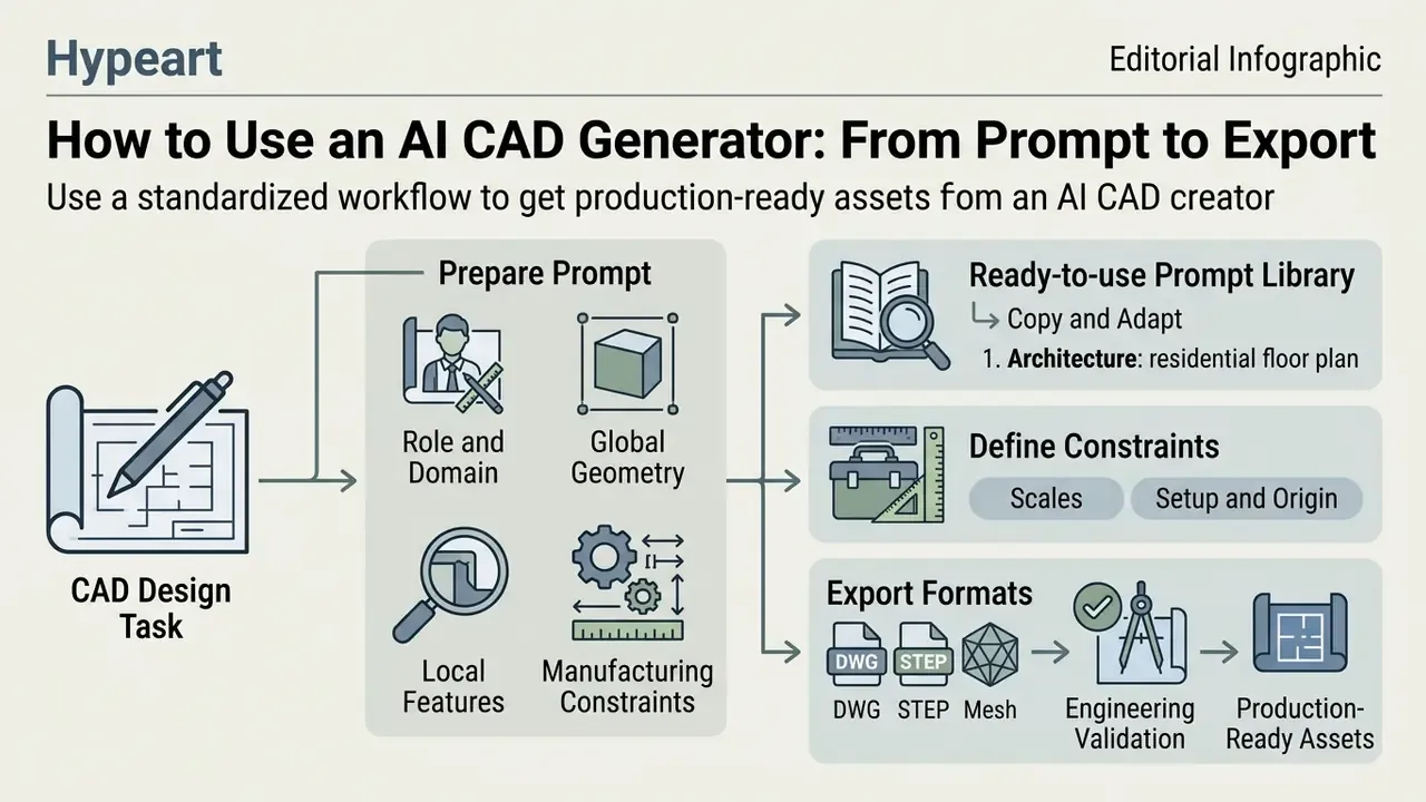
To get production-ready assets from an ai cad creator, standardise the workflow. A disciplined procedure prevents design errors and keeps transfer into professional downstream tools clean.
Define the CAD design task and prepare the prompt
Start by defining the functional role, geometric boundary conditions and technical requirements of the target component. Avoid broad conceptual requests; write structured prompts that read like formal engineering specifications. Published prompt-engineering guidance for engineering contexts (IBM Prompt Engineering Guide 2025; IDEEAS Lab Guide for Engineering Students 2025; Purdue RCAC 2026) converges on the same requirements: name the discipline, the software target, the governing standard, boundary conditions, units, precision, and the expected output format. Then iterate and version the prompt like any other controlled artifact.
A robust prompt template has five components:
- Role and domaindefine the target application ("mechanical part for aerospace bracket").
- Global geometryspecify primary bounding box dimensions ("120 mm x 80 mm x 45 mm block").
- Local featuresdetail holes, pockets, bosses and chamfers with explicit positions and tolerances ("four M6 clearance holes positioned 10 mm from corners").
- Setup and origindeclare the primary workplane and coordinate origin ("XY plane, origin at bottom-left corner").
- Manufacturing constraintsstate draft angles, minimum wall thickness, mating clearances.
Ready-to-use CAD prompt library (copy and adapt)
The following templates apply that structure to the most common production requests. Replace bracketed values with your own specification, and keep the units, standard references and origin declaration intact.
1. Architecture: residential floor plan
2. Mechanical: parametric assembly
3D CAD mechanical assembly: central shaft 20 mm diameter x 180 mm long,
one spur gear (module 2, 24 teeth) keyed at X=40 mm, two 20 mm bearing seats
at X=10 mm and X=170 mm, retaining ring groove per DIN 471.
Exploded view with numbered callouts and a parts table.
Output as STEP B-Rep topology with explicit millimetre dimensions.
Minimum 0.5 mm fillet on all internal corners; watertight manifold solids;
workplane XY, origin at shaft left face centre.
3. Electrical: control schematic
4. Product and furniture design: orthographic plus isometric
5. Patent and documentation line art
6. Interior planning: furniture layout with traffic paths
Generate, review and refine the CAD output
After you submit the prompt or reference image, the ai cad generator returns an initial design candidate. Review it in tiers, evaluating geometric topology, dimensional consistency and operational intent. Industry practice separates this into three passes: a standards-based rule check of the drawing content, a deterministic geometric comparison against reference geometry, and a marked-up visual review that pins each issue to a location on the sheet.
If the model shows inaccurate features, issue refined natural language instructions ("increase wall thickness to 3.2 mm and change fillet radius to 1.5 mm"). Iterative feedback loops measurably improve geometric fidelity.
«PR-CAD outperforms GPT-4o, Text2CAD and Text-to-CadQuery, achieving the lowest invalidity ratio (0.62) and mean Chamfer Distance (5.87) among the tested models». PR-CAD, arXiv:2604.19773 (2026). https://arxiv.org/abs/2604.19773
Single-pass outputs in the same comparison stay above a Chamfer Distance of 30.0. That is the quantitative argument for never shipping a first-generation result, and it costs you one extra loop.
Export and download CAD files for further work
Once the design meets topological and dimensional requirements, run the export. The chosen extension dictates whether downstream users can edit parametric feature histories or merely spin a static surface mesh.
For maximum editability, select neutral solid formats such as STEP (ISO 10303 AP242) or IGES for 3D geometry, and DXF or DWG for 2D drafting sheets. Reserve slicer-oriented mesh formats like STL or 3MF strictly for 3D printing or visual rendering, since they strip parametric feature trees. In BIM contexts, IFC remains the mandated open exchange format for software-to-software transfer, and exchange documentation should record format, version, processing method and responsible author. For simulation hand-off, the vendor-neutral NAFEMS VMAP interface carries material and engineering data along the CAE chain. Teams building a cost model for enterprise workflow integration can review our AI Media Pricing Guides, view the guide to unit-cost modelling, and check technical integration pathways through the AI Media API.
Free AI CAD Drawing Generator: What Free Access Includes
Evaluating a free ai cad generator or an ai cad drawing generator free download means analysing tier limits, credit allowances and export restrictions before anyone deploys the tool on real work.
Free generation, downloads and export restrictions
Most browser-based cad generator ai platforms run freemium licensing structures. A cad generator free plan typically offers a daily or monthly credit refresh (commonly 2 to 25 generations per month, depending on vendor), basic browser rendering and community file access. Documented examples span the full range: two free generations after sign-in on some text-to-CAD services, 10 per month on photo-to-3D platforms, 15 free credits per month on B-Rep-capable tools, 25 credits on general 3D generators.
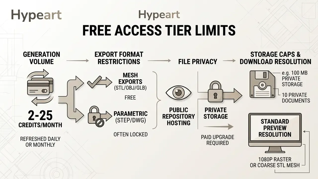
Free tiers habitually restrict the high-value outputs. You can usually generate preliminary visual concepts or export a low-resolution STL without paying, while neutral STEP solids, layered DXF files and parametric CadQuery scripts sit behind a commercial subscription. Some vendors invert this, making STEP and STL export free while capping generation count instead, so read the export matrix rather than the headline price. API access is a separate gate: several major model providers mark the free tier as "not supported" for programmatic use, which quietly kills any reproducible pipeline built on it.
Watermarks, privacy and account requirements
| Feature / Capability | Free Tier Availability | Commercial / Enterprise Tier | Governance & Risk Impact |
|---|---|---|---|
| Input Modalities | Text prompts, standard raster uploads | High-res rasters, vector blueprints, API streams | Free tier limits complex multimodal engineering inputs |
| 3D CAD Generation | Mesh-based outputs (STL, OBJ, GLB) | Parametric B-Rep solids (STEP, IGES, CadQuery) | Mesh outputs lack engineering editability and feature history |
| Export Formats | Public download, coarse mesh or raster | Multi-format vector and solid export (DWG, STEP, DXF) | STEP and DWG required for professional CAD software import |
| Watermarks & IP | Visible or invisible AI metadata watermarks | Watermark-free, explicit copyright grant | Unpaid tiers often license outputs for non-commercial use only |
| Data Privacy | Public storage, models used for AI training | Private cloud, zero data retention, SOC 2 / GDPR | Uploading proprietary designs to free tiers creates IP exposure |
| API & Automation | Frequently unsupported | Rate-limited programmatic access, SSO, audit logs | No API means no reproducible, logged pipeline |
| Unclear terms | Check the licence before use | Check the licence before use | Never assume rights that the plan text does not state |
Table 2: Free access comparison matrix for AI CAD tools across input, generation, export, watermarking, privacy and automation criteria.
Enterprise procurement and audit-trail checklist (prevents Shadow AI)
Free-tier convenience is the single biggest driver of unsanctioned tool adoption. Procurement, IT security and model-risk functions should demand documented evidence on the following before any AI CAD tool touches proprietary geometry.
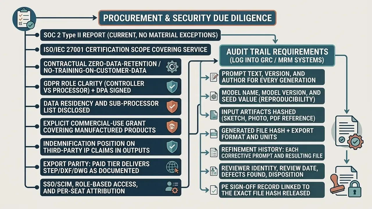
Without seed and model-version capture, an AI-generated drawing is not reproducible. And a non-reproducible artifact cannot be defended in a design review, an incident investigation, or a regulatory audit. That is the whole argument in two sentences.
Choosing an AI CAD Tool for Architecture, Engineering and Product Design
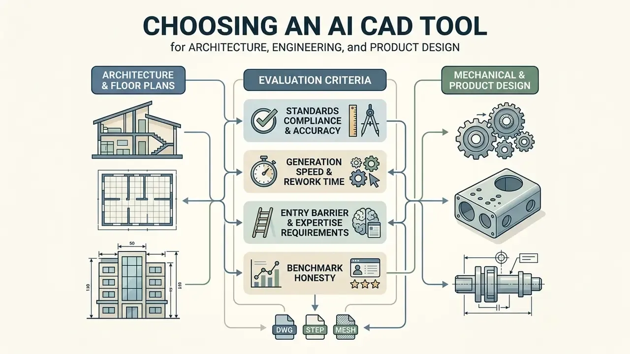
Selecting a cad ai generator or ai cad design generator means matching tool capabilities to industry standards, domain workflows and the mathematical representation your process needs. The structured evaluation logic we use when comparing AI tools for visual content generation transfers directly, with one addition: engineering tools must be judged on geometric validity, not perceived quality.
AI CAD tools for floor plans and architectural drawings
Architectural drafting needs tools that handle spatial relationships, room adjacency constraints and building envelope geometry. Specialised floor plan systems such as GFLAN (2026) use a two-stage architecture: Stage A allocates room centroids via discrete probability heatmaps, Stage B uses Graph Neural Networks to regress rectangular wall, door and window coordinates.
«GFLAN restructures layout synthesis through explicit factorization into topological planning and geometric realization, using a convolutional dual-encoder architecture in Stage A». GFLAN, arXiv:2512.16275 (2026). https://arxiv.org/abs/2512.16275
Peer-reviewed work frames this domain as a human and AI workflow rather than autonomous drafting. Floor plan generation: The interplay among data, machine, and designer (International Journal of Architectural Computing, 2024) positions the designer as an indispensable participant, and a 2025 preprint extends GNN methods to multi-storey layout generation from volumetric design inputs.
Commercial architectural tools export vector layouts as DXF or PDF for AutoCAD, Revit and ArchiCAD. That lets architects and interior designers iterate quickly on spatial configurations before manually applying scale bars, wall thickness details, structural column grids and local building code annotations. Interior specialists also use these tools for furniture layout studies, traffic-path validation and contractor-facing assembly guides. All of which still get dimensioned and code-checked by hand.
AI CAD tools for mechanical parts and product models
Mechanical engineering and industrial product design demand exact dimensional adherence, watertight surface topology and manufacturing feature recognition. Tools aimed at mechanical workflows train on large CAD repositories: the ABC dataset (more than 1,000,000 hand-designed models), DeepCAD (178,238 models) and MFCAD (15,488 models with machining features such as chamfers, pockets and threads).
Advanced platforms, including Autodesk Generative Design and AI-driven parametric code generators (Text-to-CadQuery, Ragnar CAD, ForgeCAD), produce native STEP solids tailored to CNC milling, injection moulding or additive manufacturing. Engineers use them for topology optimisation, cutting part weight while holding structural strength under applied stress loads. Peer-reviewed 2025 work also demonstrates FreeCAD driven by GPT-generated Python for 3D assembly generation, reinforcing the point that the auditable frontier is prompt-to-code rather than prompt-to-file. Anyone shortlisting a cad model generator ai for regulated production should weigh that distinction heavily. NIST's AI-in-additive-manufacturing framing lists CAD compatibility and geometric understanding as the primary selection criteria for design-generation models, and its PMI validation corpus (CATIA, Siemens NX, Autodesk Inventor, PTC Creo, SolidWorks) defines the environments any output must survive.
Evaluation criteria: accuracy, speed and CAD expertise
When benchmarking platforms for enterprise deployment, heads of engineering and technology buyers weigh four things.
- Standards compliance and accuracy. Measured through geometric Chamfer Distance, Hausdorff distance, point-cloud distance, command-level F1 scores and program invalidity ratios. Leading published systems report invalidity ratios near or below roughly 1% on complex parts (FutureCAD around 1.01%, PR-CAD 0.62), but that performance is conditional on task difficulty.
«Text2CAD-Bench shows models achieve acceptable results on L1-L2 tasks, while performance degrades substantially on advanced L3 features; text-to-CAD remains unsolved beyond basic geometry». Text2CAD-Bench, arXiv:2605.18430 (2026). https://arxiv.org/abs/2605.18430
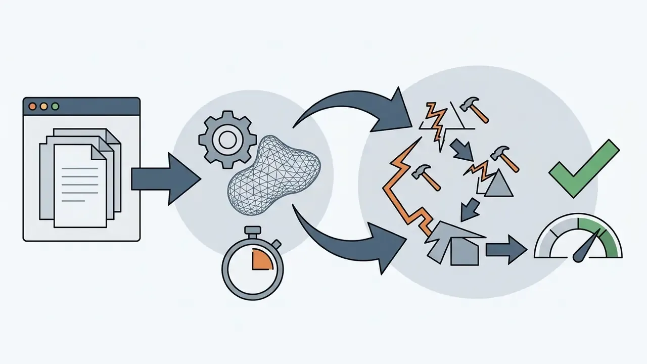
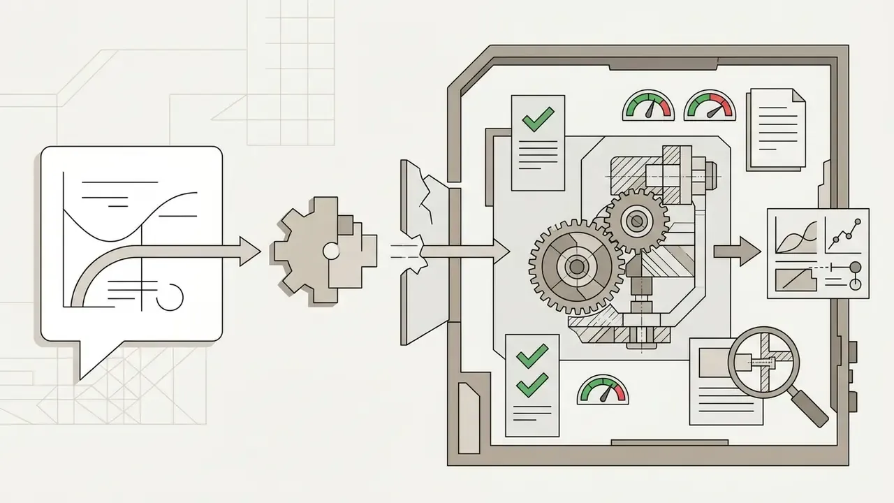
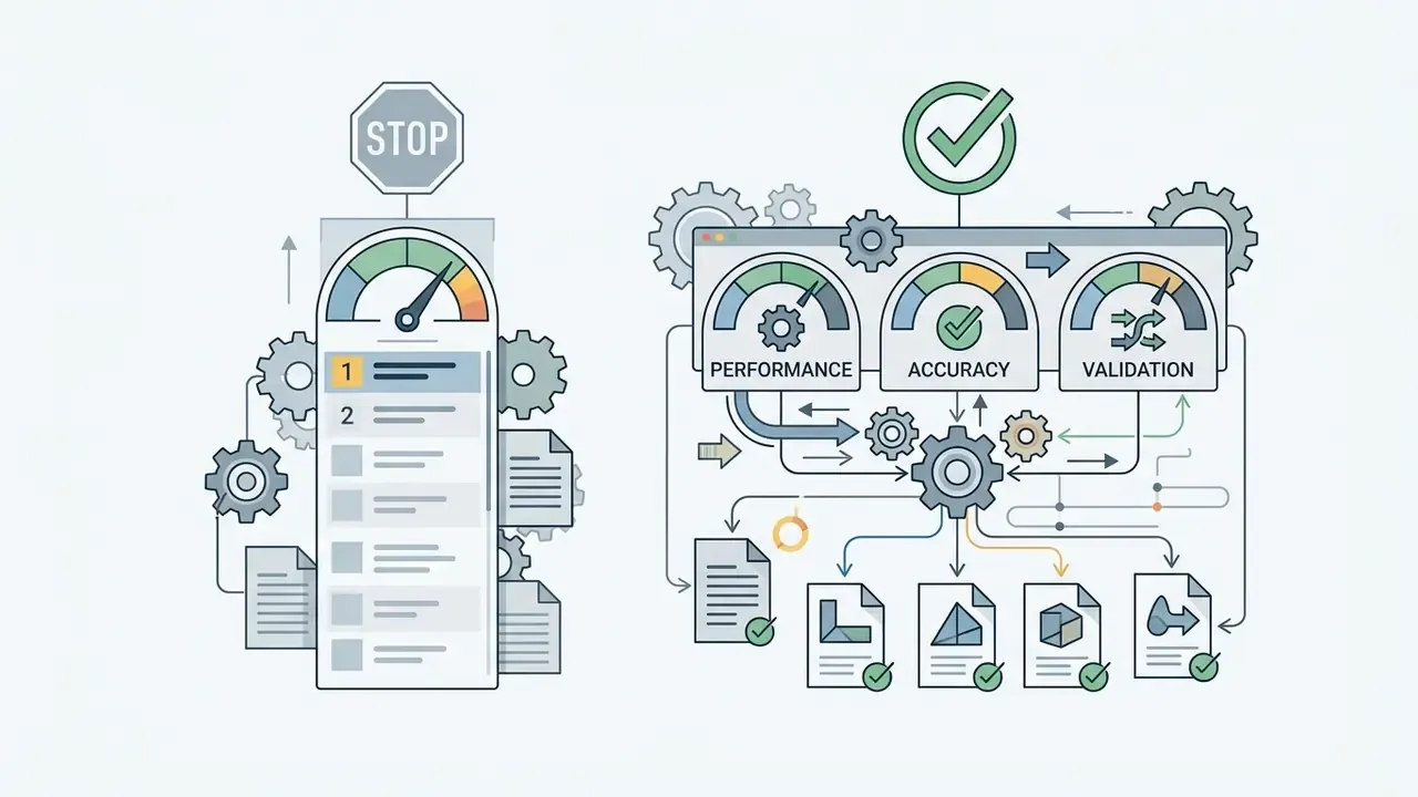
«CADBench evaluated 11 systems on 18,000 samples and identified three recurring failures: quality degradation with rising complexity, brittleness under modality shift, and metric-dependent rankings». CADBench, arXiv:2605.10873 (2026). https://arxiv.org/abs/2605.10873
Commercial Use, Accuracy and Engineering Validation of AI-Generated CAD Drawings
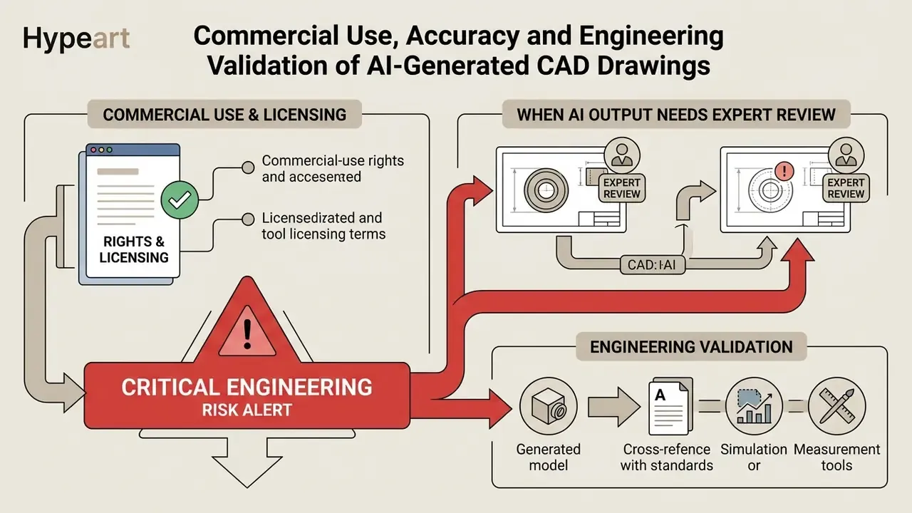
Deploying ai generated cad drawings or using ai for cad drawings on commercial projects raises licensing questions and engineering safety duties at the same time. Working from an unverified output in structural, aerospace or industrial manufacturing carries severe financial and operational risk, and the exposure lands on the signing engineer, not the vendor.
Commercial-use rights and tool licensing
Commercial rights to AI-generated assets are governed by tool-specific end-user licence agreements and by legal doctrine that is still moving.
Most commercial platforms grant full worldwide commercial rights, including modification, distribution and manufacturing, only on paid enterprise tiers. Documented examples show paid plans conveying perpetual, transferable, sublicensable licences covering products, media and physical manufacturing, while outputs generated without a paid plan are licensed for personal, non-commercial use only. Other vendors frame outputs narrowly as "internal business use" and warn explicitly that AI outputs may contain errors and third-party IP claims. A minority grant full commercial rights even on free exports. The variance is total, so plan-level terms are the only reliable source.
Design firms should read those terms carefully to confirm that generated CAD models do not infringe training data copyrights or third-party intellectual property before a product ships. Organisations reviewing AI Media Commercial-Use rights across AI ecosystems can inspect our licensing guide, compare options on active IP disputes, and review platform terms in the Canva AI Generator commercial analysis.
When AI-generated CAD output needs expert review
These generators function as powerful pre-validation drafting assistants. They are not engineering authorities. Synthetic models routinely introduce invisible defects: non-manifold edges, micro-gaps between faces, unconstrained sketch dimensions, invalid stress distribution assumptions.
«Drawing2CAD reframes CAD model generation as a sequence-to-sequence learning problem, exploiting the rich geometric information in vector drawings to infer extrusion and revolution operations». Drawing2CAD, arXiv:2508.18733, ACM MM (2025). https://arxiv.org/abs/2508.18733
Even where a system reconstructs geometry from a fully dimensioned vector drawing, the most constrained input available, the output remains a hypothesis about intent rather than a verified design.
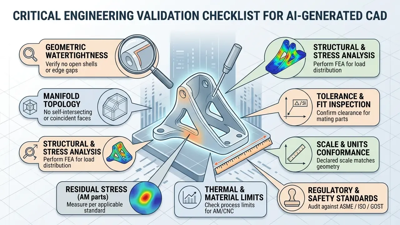
Before releasing AI-generated drawings or 3D models to production, manufacturing or construction, a certified professional engineer or senior designer must run an independent audit. Standards such as NASA MSFC Verification Handbooks and Hanford Design Verification Procedures require formal calculations, physical testing, alternate calculation, independent design review, or some combination, and they require controlling documents to be complete before verification counts as finished. NIST IR 8538 (2024) adds that in-process monitoring and non-destructive evaluation are necessary in additive manufacturing, because hidden defects and distortion can survive the build. NIST tolerance-specification work warns separately that AM geometric capability is not equivalent to conventional machining and must be specified against real process limits.
CRITICAL ENGINEERING RISK ALERT
FAQ: AI CAD Drawing Generators
Can an AI CAD generator export a native, editable DWG file?
Rarely, and almost never in one step. Verified official documentation confirms STEP export for several CAD and configurator tools, and DWG export for specific CAD/GIS utilities, but no reviewed official page demonstrates a general AI-native, fully constrained DWG export as a core generative feature. Practical route: generate STEP or SVG, then import via STEPIN or DXFIN, or trace in AutoCAD. Marketing that promises an instant ai autocad generator with layered DWG output deserves a demo request, not a purchase order.
Is the output accurate enough for CNC or construction?
Not without verification. Published benchmarks show good performance on basic and intermediate geometry, with clear degradation on advanced features. Treat every output as a draft requiring a geometric audit, FEA where loads apply, and PE sign-off.
What is the difference between STEP and STL, in one sentence?
STEP carries exact B-Rep solid geometry (and in AP242, PMI and product structure) suitable for engineering edits and CNC, while STL carries a triangular facet approximation suitable only for slicing and visual review.
Can I upload my own sketches or existing plans?
Yes. Text, hand sketches, photographs, scanned PDFs and vector drawings are all supported input modalities across the tool landscape. Verify data-retention terms before you upload anything proprietary or patent-pending.
How do I get accurate dimensions?
Declare them. State the origin, units, bounding box, feature coordinates, tolerances and target scale explicitly in the prompt. Undeclared dimensions get inferred from the training distribution, and that is the primary cause of dimensional drift.
Can I use free-tier outputs commercially?
Sometimes, though the default across sampled EULAs is no: free outputs are frequently licensed for personal, educational or internal-testing use, with commercial rights reserved for paid tiers. A minority of vendors grant full commercial rights on free exports. Read the plan-level terms rather than the pricing page.
Do AI-generated drawings need to be labelled as AI-generated?
Under European Commission AI transparency guidance (2026), providers must apply machine-readable marking so AI-generated or manipulated content is detectable, with visible watermarks and labels as complementary measures. Internally, log AI provenance on every artifact regardless of jurisdiction.
How does this compare to AutoCAD, SolidWorks or SketchUp?
It is a concepting and drafting-acceleration layer, not a replacement. Use AI for the first large block of speed work (ideation, layout options, baseline solids), then take the final pass into your production CAD tool, where constraints, standards and drawing management live.
Which formats should I request for each downstream use?
STEP or CadQuery code for engineering edits and CNC. DXF or DWG for 2D drafting sets. IFC for BIM exchange. STL or 3MF for slicing. GLB, OBJ or FBX for visualization. SVG or PDF for patent and manual line art.
What should we log for auditability?
Prompt text and version, model name and version, seed value, input file hashes, output file hash, units, refinement history, reviewer identity, and PE sign-off tied to the exact released file hash.
Strategic Summary and Next Steps
Bringing an ai cad drawing generator into enterprise workflows delivers genuine speed during ideation, preliminary drafting and concept modelling. Sustainable value, though, comes from balancing that speed against model governance, explicit licensing compliance and rigorous engineering validation. Fast drafts with no evidence trail create rework, not throughput.
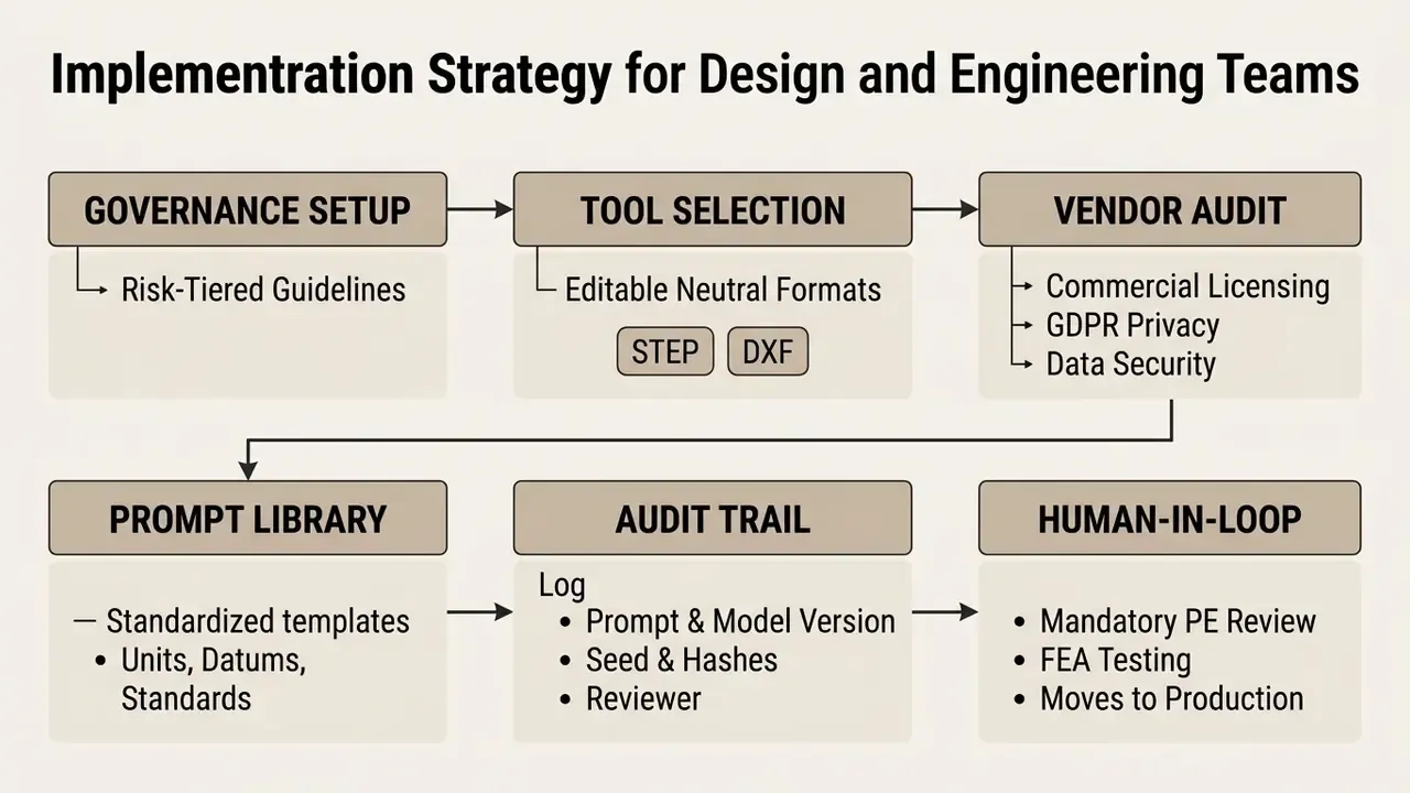
Appendix A: Risk-tiering matrix for AI CAD use cases
Not every generated drawing warrants the same control burden. Tiering keeps review effort proportionate, which is usually what unblocks adoption.
| Risk tier | Typical use case | Minimum controls | Sign-off owner |
|---|---|---|---|
| Tier 1: low | Internal ideation sketches, moodboards, layout options never issued externally | Logged prompt and model version; no confidential inputs | Design lead |
| Tier 2: moderate | Client-facing concept plans, marketing renders, internal documentation line art | Tier 1 plus licence check, watermark and provenance label, dimensional sanity check | Project manager |
| Tier 3: high | Coordination drawings, non-structural components, prototype tooling | Tier 2 plus full geometric audit, units and scale conformance, seed-fixed reproducibility | Senior engineer |
| Tier 4: critical | Load-bearing structures, pressure parts, safety-critical assemblies, regulatory submissions | Tier 3 plus FEA or physical test, independent design review, PE sign-off bound to file hash | Licensed professional engineer |
Two notes on limits. First, tier assignment should be made before generation, not after someone likes the result. Second, this matrix is illustrative; calibrate the thresholds against your own risk appetite, insurance position and governing standards.
Appendix B: Key terms used in this guide
- B-Rep (boundary representation) exact mathematical description of a solid through faces, edges and vertices. Editable engineering data.
- Mesh faceted approximation of a surface. Fine for viewing and slicing, wrong for tolerance work.
- Chamfer Distance average distance between generated and reference geometry. Lower is better.
- Invalidity ratio share of generated outputs that fail to produce a valid solid on execution.
- Seed the random initialisation value that, when fixed, makes a generation repeatable.
- Shadow AI unsanctioned tool use outside approved inventory, access controls and logging.
About the review
This guide is maintained by our engineering-content team and reviewed against primary sources: ISO 128-1:2020, ISO 129-1:2018, ISO 10303-242 (STEP AP242), NASA GP-435 Vol. II Rev. C, NASA MSFC verification handbooks, Autodesk AutoCAD documentation, Library of Congress DWG format analysis, NIST CAD and PMI validation materials, and peer-reviewed 2024-2026 publications on text-to-CAD and image-to-CAD generation. Expert commentary contributed by Marcus Hale, AI Governance and Model Risk Specialist, the author whose illustrative practice covers model-risk frameworks, Shadow AI containment and evidence-based autonomy limits for generative systems in regulated engineering environments. For broader directory access, see the overview in our central reference archive.