TL;DR, five takeaways for decision makers
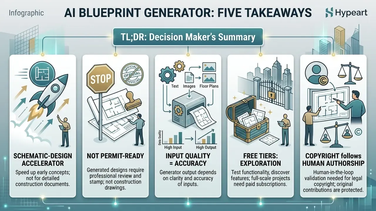
- AI blueprint generators are schematic-design accelerators, not document-production engines. A 2025 systematic review of 161 papers found generative AI concentrated in schematic design, with detailed construction documentation still underexplored and 60.9% of evaluations comparative rather than field-verified.
- Nothing generated is permit-ready. Building permits are issued only against plans stamped and signed by a licensed architect or professional engineer in the governing jurisdiction.
- Accuracy tracks input quality. Clean vector PDFs and precise prompts yield the highest fidelity. Photographs, handwritten scans and vague briefs produce geometric artifacts and floating room boundaries.
- Free tiers are for exploration. Expect capped credits, watermarked raster exports, no vector DWG/DXF/IFC, and personal-use-only licensing. Paid tiers unlock vector layers, BIM pipelines and commercial rights.
- Copyright follows human authorship. Purely AI-generated output is ineligible for copyright protection. Only human-authored modifications are protectable, and AI-generated material must be disclosed at registration.
How to read this guide
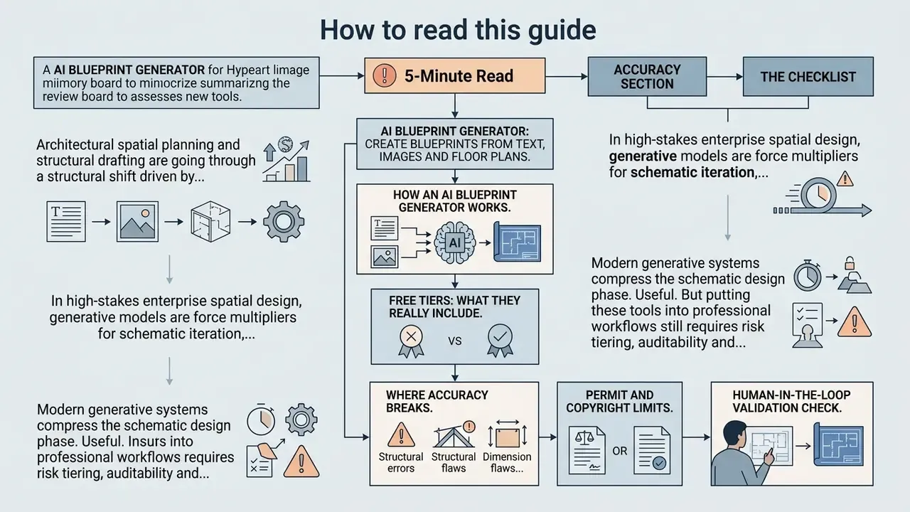
The order below is deliberate, and it mirrors how a review board actually works through a new tool. First the definitions, because "blueprint", "floor plan" and "construction drawing" carry different liability weight. Then the mechanics of generation, the output classes, and the real shape of free-tier limits. After that comes the part most vendors skip: accuracy evidence, a validation checklist you can log against, data-handling requirements for sensitive facility geometry, and a selection matrix keyed to your inputs and deliverables. The FAQ closes the loop on the narrow practical questions, and the appendix records what was corrected and what remains unverified.
If you only have five minutes, read the accuracy section and the checklist. Those two carry the risk.
Architectural spatial planning and structural drafting are going through a structural shift driven by generative artificial intelligence. An ai blueprint generator lets architects, construction managers and enterprise real estate leaders turn natural language prompts, hand-drawn sketches and legacy raster files into parametric floor plans and CAD-ready layouts.
Modern generative systems compress the schematic design phase. They synthesize layout options quickly, evaluate room adjacency, and emit structured data that downstream Building Information Modeling (BIM) platforms can actually read.
«LLM-driven pipelines convert natural language prompts into coordinate-based JSON, then programmatically construct 3D models in Autodesk Revit.»
Useful. But putting these tools into professional workflows still requires risk tiering, auditability and strict human-in-the-loop validation. That is the whole argument of this page.
What is an AI blueprint generator and what can it create?
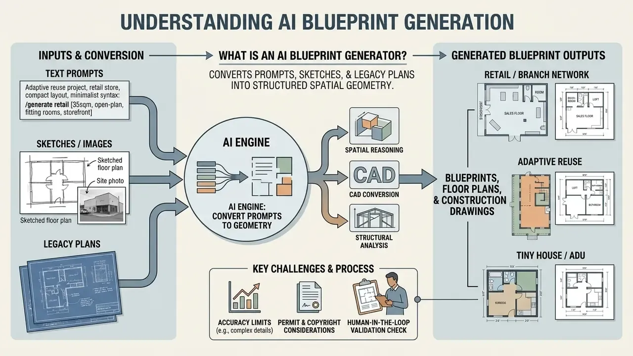
In two sentences: an AI blueprint generator converts prompts, sketches or legacy plans into structured spatial geometry. It outputs schematic 2D plans, 3D massing and vector CAD/BIM assets, never certified construction documents.
An ai blueprint generator is an artificial intelligence platform that converts spatial constraints, textual prompts or reference images into structured architectural schematics. These systems translate design intent into coordinate-based 2D floor plans, 3D space models or vector CAD files.
By leaning on machine learning architectures such as conditional Generative Adversarial Networks (cGANs), diffusion models and Large Language Models (LLMs), an ai blueprint maker automates a large slice of space planning. The practical payoff shows up in early feasibility studies, client presentations and preliminary cost estimating.
Commercial implementations in this category advertise three broad output families: code-aware construction-document starting sets (architectural, structural, MEP, energy-compliance and life-safety sheets), plan, roof-plan, elevation, section and schedule packages, and construction-economics artifacts such as first-pass takeoffs, bills of materials and quantity groups exported to PDF, CSV, XLSX, DWG or DXF. The breadth is real. The legal status of the output is not, and every vendor in this class stops short of claiming permit-grade deliverables.
Visual blueprints, floor plans and construction drawings
Visual blueprint designs give you a high-level aesthetic representation of an architectural concept, suitable for spatial visualization and client reviews. A floor plan is something narrower: a horizontal section through a single building level, showing wall arrangements, room dimensions, door swings and circulation paths.
«A floor plan is a horizontal section showing the position, dimensions and interrelation of rooms, corridors, walls and openings.»
The terminology hierarchy matters commercially, because it defines liability boundaries.
| Document class | What it shows | Where AI is useful | Where AI stops |
|---|---|---|---|
| Blueprint (legacy term) | Historically a cyanotype reproduction, white lines on blue paper, of any drawing | Concept imagery, marketing visuals | Not a distinct technical drawing class in modern standards |
| Floor plan | Horizontal cut of one level: walls, openings, stairs, labels, dimensions, scale, north arrow | Layout generation, adjacency optimization, unit-mix studies | Dimensional certification, structural sizing |
| Architectural plan set | Plans, elevations, sections, site plan for the building design | Variant generation, elevation massing, section previews | Coordination with engineering disciplines |
| Construction drawings | Working documents: assemblies, details, specifications, MEP coordination | Draft sheeting, annotation, schedule population | Permit issuance, stamping, liability |
Unlike concept imagery, a full construction drawing set carries detailed structural, mechanical, electrical and plumbing (MEP) specifications required for site execution and regulatory permitting. Modern blueprint ai generator tools are strong at schematic floor plans. They do not automatically produce certified construction document sets without manual engineering input. Russian SPDS practice (GOST 21.501-2018) illustrates how demanding real documentation is: sections must carry axes, level marks, wall thicknesses and the composition of multilayer assemblies, with cut contours drawn in thick primary linework. Generative image models approximate those conventions. They do not guarantee them.
Blueprint generation from text, image and existing plans
Text-to-blueprint workflows use LLM prompt parsers and diffusion engines to turn plain-language descriptions into spatial coordinates. You can specify room counts, square footage limits and functional adjacencies directly in natural text.
«Text-prompt floor plan generation from prompts, sketches and reference images shows persistent limits in scale fidelity and boundary crispness.»
Architecturally, the strongest text pipelines are two-stage. An LLM extracts object boxes, object-level descriptions and background context, then a layout-to-image diffusion stage renders and iteratively refines geometry against that layout. That is the approach documented in LLM Blueprint (2023) and echoed in 2025 Revit-integration workflows.
Image-conditioned generation accepts uploaded hand sketches, site photographs or scanned PDFs. Updated: computer-vision pipelines run preprocessing, text detection and optical character recognition (OCR), floor-plan parsing, wall tracing and symbol segmentation, then assemble a structured building model from the extracted rooms, walls, doors and semantic labels. Peer-reviewed floor-plan recognition work demonstrates room-structure, room-type and size recognition followed by vectorized 3D reconstruction. Independent verification of per-symbol accuracy rates for any given commercial vendor remains thin, so treat vendor-published parsing scores as unaudited claims that still need data behind them. Multi-conditional platforms ingest existing building footprints and bubble diagrams to generate diverse, topologically compliant layouts. Teams preparing raster sources can review general image preprocessing and photo-editor workflows before ingestion.
Actionable prompt framework for text-to-blueprint
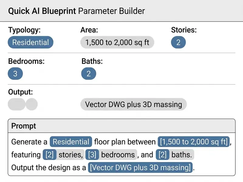
To generate precise vector layouts, structure your natural language input in this parameter order:
Three further prompt patterns cover the most common enterprise cases:
Prompt-quality research supports this discipline directly. Automated prompt rewriting improved prompt-image consistency by up to 24.9% on MSCOCO and PartiPrompts (2024), and CHI-published text-to-image design guidance recommends emphasizing subject and style keywords while running several seeds, because outputs stay stochastic. When you upload reference geometry, preserve it: professional prompting guides for architectural image tools require that walls, openings, ceiling heights, proportions, camera position and spatial layout remain unchanged.
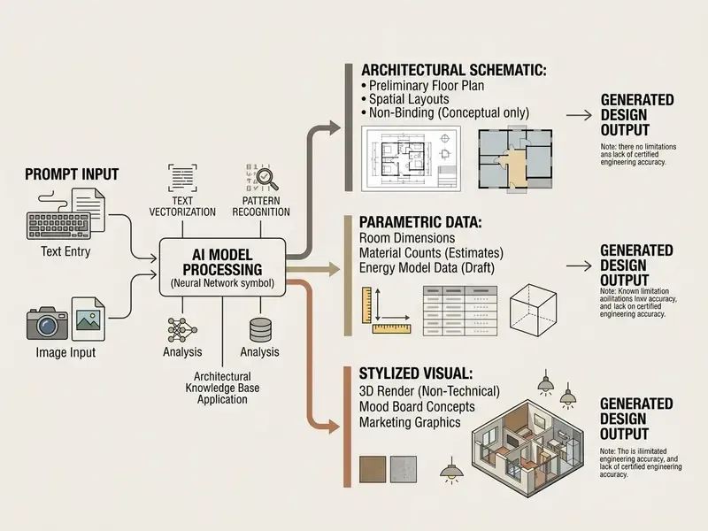
| Input branch | Typical inputs | Typical output assets |
|---|---|---|
| Text prompts | Natural language briefs, spatial constraints, adjacency rules | Schematic layouts and coordinate JSON, feasibility space models |
| Raster images and sketches | Hand-drawn concepts, facade and site photographs | Vectorized DWG/DXF, 3D massing renderings |
| Footprints and CAD files | Bubble diagrams, legacy CAD or BIM PDFs | Code-aware floor plans, parametric BIM assets |
How does an AI blueprint generator work?
In two sentences: the engine parses spatial intent, synthesizes draft geometry, then compiles vector or BIM files. Every stage is inspectable, and the review stage is the one that decides whether the output is usable.
An ai blueprint generator from text works by translating input parameters into structured spatial coordinates, generating draft vector geometries, then refining topological relationships. Spatial parsing, layout synthesis and file compilation run in sequence.
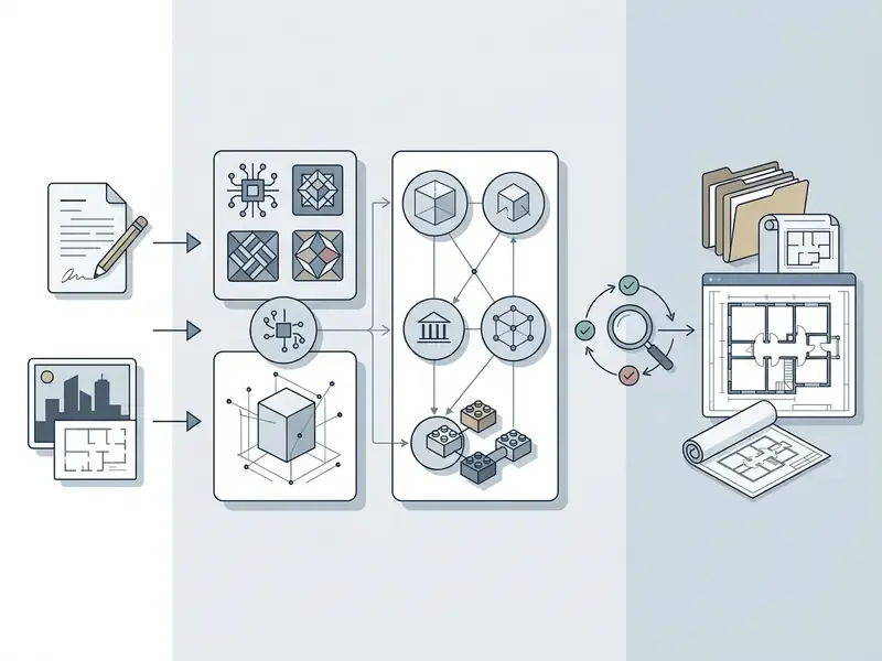
Describe the blueprint or upload an image
Generate, review and customize the first version
Once the input lands, the neural processing pipeline generates an initial layout draft. The system checks topological adjacency, room proportions and door placements against trained spatial benchmarks.
«Evaluation of generative image systems is structured around image realism, prompt adherence and human judgment, refined through pilot rounds.»
Users then review the draft inside an interactive workspace. Customization tools let operators move partition walls, modify line weights, update room labels and trigger regeneration cycles to resolve spatial overlaps. NIST programme materials also formalize the iteration loop itself: evaluation plans are adjusted and finalized after round-table review, and reusable scenarios let teams vary foundational conditions instead of testing every possible case. That pattern transfers directly to firms writing internal acceptance criteria for AI layouts.
Download, share and use the generated blueprint
After iteration, the platform compiles the layout into standard distribution formats. Exports include vector CAD assets (DWG, DXF), open BIM models (IFC) and publication-ready PDFs. Broader interoperability targets documented across the CAD/BIM ecosystem include IFC (ISO 16739-1, with STEP clear-text and XML serializations), COBie for tabular handover, CityGML for urban context, plus DWG/DXF, DWF/DWFX, DGN, STEP/AP214, SAT, FBX and OBJ for downstream modelling.
These files feed architectural production software, cost estimation databases and client presentation decks. Enterprise teams evaluating programmatic ingestion can study comparable generative API integration and cost patterns before committing to a vendor's endpoint contract, and check commercial tiering against project volume on the current plan pricing overview.
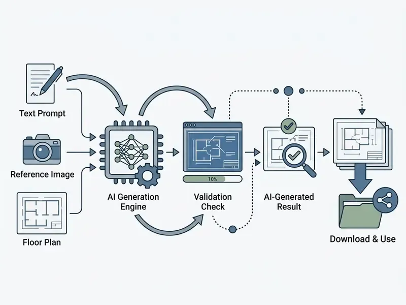
- Step 1, input definition. Provide natural language design prompts or upload clean raster and sketch files with clear structural boundaries.
- Step 2, AI geometry synthesis. Neural algorithms parse spatial constraints, running diffusion or LLM coordinate mapping to build a layout draft.
- Step 3, verification and customization. Review spatial adjacencies interactively, adjust partition walls, modify line weights, re-run sub-sections.
- Step 4, vector compilation and export. Compile approved layouts into DWG, DXF, IFC or PDF for downstream CAD/BIM integration.
- Step 5, licensed review and sign-off. Route the export to a licensed architect or professional engineer for correction, stamping and permit submission.
What types of blueprints can AI generate?
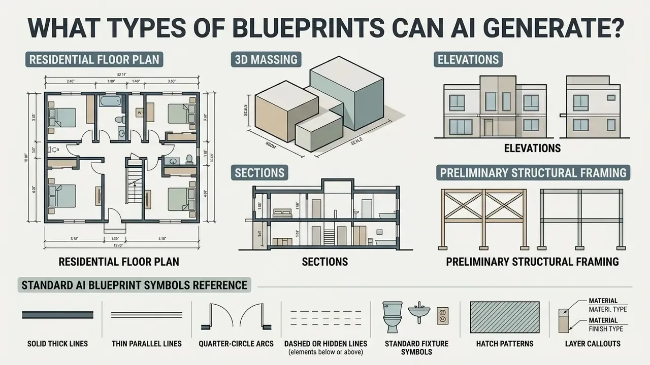
In two sentences: output spans residential floor plans, 3D massing, elevations, sections and preliminary structural framing. Depth depends on the training corpus and how tightly the tool is wired into BIM.
A modern blueprint creator ai platform generates diverse architectural assets, from initial 2D residential floor plans to complex multi-layered structural frames. Breadth depends on the underlying training corpus and BIM integration depth.
Home design, floor plans and 3D plans
Residential space planning is still the most developed domain for AI generation tools. Systems produce fully dimensioned 2D single-family floor plans, apartment unit layouts and interior arrangements complete with furniture placement vectors. The academic precedent is deep: generative frameworks have learned from site layouts and floor-plan examples using Bayesian networks with MCMC sampling, and conditional GAN families (pix2pix, BicycleGAN, SPADE) have been benchmarked specifically for furniture layout inside fixed room boundaries.
Advanced platforms convert 2D planar coordinates into isometric 3D models automatically, and commercial tools accept PNG, JPG, PDF, DXF or DWG uploads to rebuild an editable 3D project from a flat plan.
«FloorplanDiffusion reaches FID 8.36 on RPLAN, a 74.2% improvement over baselines, with 54.4% expert Turing-test plausibility.»
Standard AI blueprint symbols reference
When reviewing AI-generated schematics, the engine applies standard ISO 128 and AIA graphic conventions. Reading them correctly is the fastest way to catch a hallucinated layout.
- Solid thick lines
- primary structural load-bearing walls and exterior boundaries.
- Thin parallel lines
- window assemblies, glazing panels, interior partitions.
- Quarter-circle arcs
- door swing paths showing hinge orientation and required clearance.
- Dashed or hidden lines
- overhead beams, ceiling bulkheads, structural trusses, subterranean utility runs.
- Standard fixture symbols
- MEP elements such as HVAC diffusers, plumbing stacks, electrical outlets and distribution panels.
- Hatch patterns and layer callouts
- multilayer assembly composition, insulation, material zones. SPDS-style sections additionally carry axes, level marks and wall thicknesses.
- Legend or key block
- every drawing set defines its own symbol dictionary. If the AI output omits the legend, the drawing is not reviewable.
ISO 128-1 covers both 2D and 3D technical drawings. ISO 128-2 defines the line types used across drawings, plans and maps, ISO 128-3 handles views and sections, and ISO 7519 sets general principles for construction drawings used for general arrangement and assembly. AIA CAD Layer Guidelines, incorporated into the U.S. National CAD Standard, govern layer naming across architectural and structural disciplines.
Architectural, technical and construction drawing formats
Beyond residential floor plans, specialized AI tools synthesize orthographic elevation drawings, building longitudinal sections and preliminary structural framing plans. These outputs follow established drafting standards, including AIA layer naming conventions and ISO 128 linework rules.
«PCDM is trained on real structural drawings and generates shear walls that respect horizontal and vertical boundaries and elevator core geometry.»
In structural engineering research, Probabilistic Conditional Diffusion Models (PCDMs) predict shear wall placements and core tube configurations around elevator shafts directly from architectural inputs. These technical drawings give professional engineering review a foundation. They do not replace it.
Exploded orthographic and layer-separated outputs
Advanced AI blueprint engines synthesize exploded orthographic views that decompose a building schematic into distinct vertical planes. Instead of a flat image, the spatial engine isolates:
- Structural grid and foundationcolumn centerlines, footings, load-bearing piers.
- Floor slabs and deckinghorizontal diaphragms showing stairwell openings and plumbing penetrations.
- Partition and wall assembliesinterior wall locations with integrated door swings and window voids.
- Facade and curtain wall systemsexterior envelope components, glazing divisions, structural cladding layers.
- Roof plane and overhead systemsroof pitch geometry, parapets, mechanical plant zones.
Presentation-grade exploded diagrams usually ship as high-resolution raster (PNG) with varying line weights and vector-style rendering. Where the receiving team needs geometry rather than a picture, only tools exposing layer-separated DWG/DXF or IFC will serve the workflow. Layer separation is also what makes output auditable: a reviewer can switch off the facade layer and check whether the structural grid is genuinely continuous, which flat generated imagery hides completely.
Free AI blueprint generator: what is included and what may be limited?
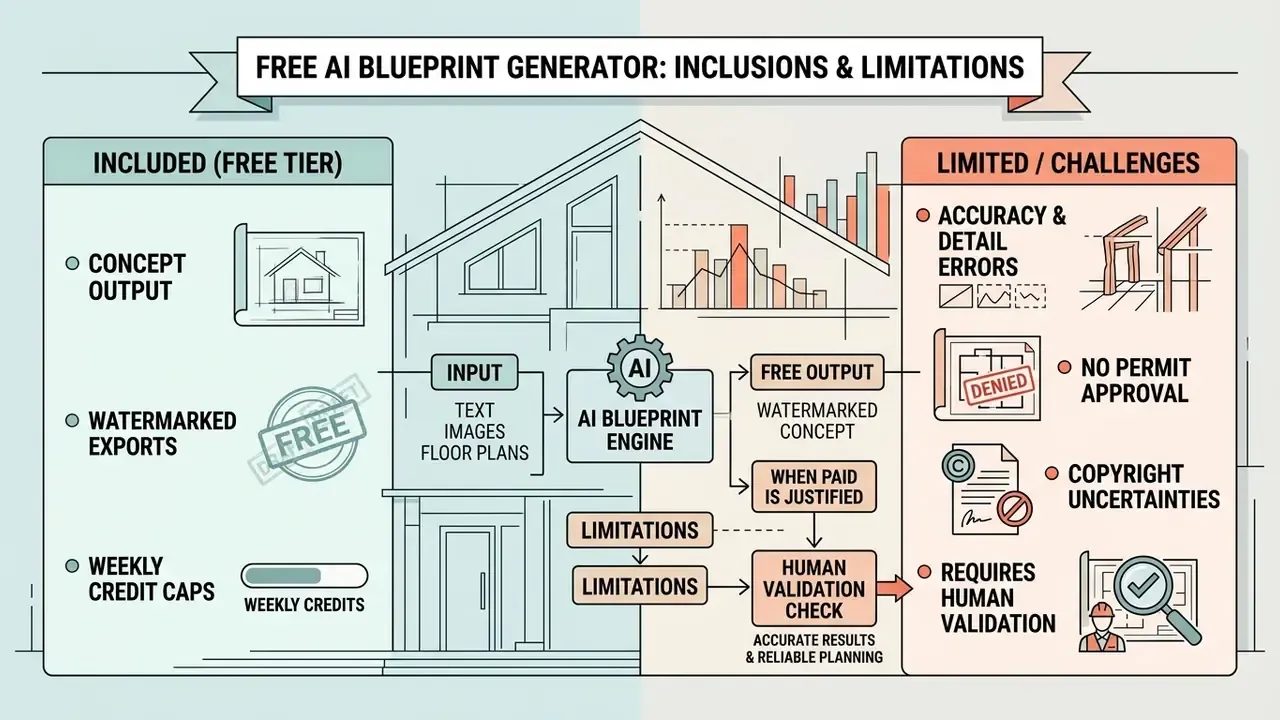
In two sentences: free tiers deliver watermarked concept output under weekly credit caps. Vector export, 3D, layer control and commercial rights sit behind paid plans.
A free ai blueprint generator covers essential drafting for non-commercial exploration, concept generation and academic testing. Free tiers also enforce firm operational constraints, partly to protect compute and partly to nudge upgrades. The economics of adjacent generative categories look similar: the structure of free-tier limits, export restrictions and paid upgrades repeats across creative AI software with very little variation.
Free generations, credits and iteration limits
Export quality and features in free blueprint makers
Free blueprint tools generally restrict exports to standard-definition raster images (PNG, JPG) stamped with visible vendor watermarks. Documented free tiers in adjacent AI-visual categories export PNG/JPG at 72 DPI or cap resolution at 1K, while paid tiers reach 2K to 4K. Higher-tier vector formats such as DWG, DXF and IFC usually sit behind the paywall.
Free modes also tend to disable 3D model generation, layer separation controls and high-resolution CAD exporting. Some products state plainly that the 3D view is a mechanical render with no exportable CAD or STL geometry. Those limits are what keep unverified free outputs out of commercial building production pipelines, and honestly that is not a bad thing.
When a paid tool is justified
Upgrading to a professional paid plan becomes necessary when you need uncompressed vector exports, custom layer mapping and full commercial usage rights. Paid tiers unlock private model hosting, team collaboration environments and automated BIM integration scripts. Published paid thresholds across the generative-tooling market show the pattern: general assistant plans at about $20 per month for roughly 5× free usage and priority access, architecture-oriented Pro tiers at roughly $30 to $60 per month for commercial licensing, private generations and higher-resolution output, annual unlimited-project plans starting near $499 per year, and enterprise document-production platforms materially above that. Some CAD vendors also expose AI capabilities as paid add-ons rather than base features, which is easy to miss in a budget line.
Three triggers justify the spend in practice: the output must be commercially licensed, throughput exceeds free credits, or the required capability (vector layers, BIM export, private hosting) is simply absent from the free tier. Model the totals with your finance team using the available cost calculators before committing to an annual contract.
During a commercial office modernization project, a design team needed rapid CAD asset generation across 12 floor levels. Upgrading to an enterprise subscription secured raw DXF vector exports and custom layer separation, which the team credited with saving in excess of 80 hours of manual drafting. That figure is a practitioner estimate, not an independently audited measurement. Model your own baseline drafting hours before quoting savings to a board, because the number moves with drafting standards and reviewer seniority.
Before signing, read the licensing question directly against documented commercial-use terms for generative AI outputs. Usage rights, not features, are the most common source of downstream legal exposure.
| Feature / capability | Free AI blueprint generator | Paid or enterprise AI blueprint tool |
|---|---|---|
| Generation credits | Small weekly allowance (commonly ~5 to 12 credits or projects, vendor-specific) | Unlimited or high-volume enterprise quotas |
| Export formats | Low-res PNG / JPG (watermarked, often 72 DPI or 1K) | High-res PDF, DWG, DXF, IFC, STEP, FBX, OBJ |
| 3D modeling & BIM | Basic 2D preview or non-exportable render | Full 3D isometric views and parametric BIM assets |
| Customization & layers | Single raster layer, fixed styling | Multi-layer separation, AIA layer naming, line weight control |
| Commercial rights | Personal or educational use only | Full commercial usage rights and contractual assignment |
| Collaboration & API | Single user workspace | Team sharing, central asset hub, API access |
| Deployment & data handling | Public multi-tenant cloud | Private cloud, VPC or on-premise options, retention controls |
| Hidden cost to budget | Manual redraw of unusable output | Human-in-the-loop validation hours plus licensed review fees |
Read the last row twice. It is the one that usually breaks a naive ROI model, because control cost and residual risk rarely appear in the vendor's own arithmetic.
How accurate are AI-generated blueprints for professional and commercial use?
What affects AI blueprint accuracy?
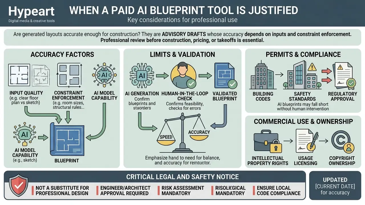
AI blueprint accuracy depends on input data clarity, prompt specificity and algorithmic constraints. Low-resolution scans or ambiguous briefs introduce geometric artifacts, non-standard wall thicknesses and floating room boundaries.
«Input data quality is a primary risk factor for generative systems; low image quality yields noise, artifacts and incoherent features.»
The NIST Generative AI Profile also treats output correctness, hallucination and traceability as core risks. Those are precisely the failure modes that propagate silently into construction documents when a drawing looks plausible but is dimensionally wrong.
Specialized optimization techniques improve layout stability measurably. Updated: applying Reinforcement Learning with Verifiable Rewards (RLVR) to layout-generating language models has been reported to achieve a 94% relative reduction in topological compatibility errors versus baseline models, by penalizing overlapping rooms and adjacency violations through verifiable reward functions.
«RLVR applies verifiable reward functions penalizing overlapping rooms and adjacency violations, cutting compatibility errors by 94%.»
Vendor-reported accuracy in this category also varies sharply by input type: roughly 80% on simple inputs, 90 to 95% only on clean vector CAD PDFs, and materially lower on photographs or complex multi-level layouts. These figures are not comparable across vendors, because they mix schematic-room-layout scoring, IoU spatial accuracy and internal parsing-accuracy metrics. Same percentage sign, different measurement entirely.
Review before construction, pricing or takeoffs
Treat AI-generated drawings as advisory preliminary concepts, never as final engineering specifications. Material takeoffs, structural framing calculations and cost estimates derived straight from raw AI output carry real financial and physical risk.
«AI output is advisory, must not be treated as binding, and AI-supported evaluations must be cross-checked with conventional methods and technical judgment.»
Commercial use, ownership and professional approval
Legal ownership of AI-generated spatial designs turns on human creative involvement.
«Material generated wholly by AI is not copyrightable; protection extends only to sufficient human-authored expressive elements.»
Registration guidance reinforces the practical consequence. AI-generated content above a de minimis threshold must be excluded from the application and disclosed, so ownership claims attach only to the human contribution: custom modifications, original spatial arrangements, human-authored detailing.
Commercial construction regulation adds a second constraint. Building permits are issued exclusively against plans stamped and signed by a licensed professional architect or engineer.
«Building officials must verify the preparer holds a current licence; before the construction permit is issued, drawings must be stamped and signed by the architect.»
Comparable rules exist elsewhere. Georgia Code § 43-4-16 requires architectural documents issued to obtain a building permit to be sealed by the architect and signed across the seal, and 2025 Philippine Supreme Court jurisprudence confirms that only registered and licensed architects may prepare, sign and seal architectural documents. An AI model cannot hold legal liability, and it cannot sign permit documentation. That is the whole point.
CRITICAL LEGAL AND SAFETY NOTICE:
Human-in-the-loop validation checklist
In two sentences: this is the minimum review pass before an AI layout enters CAD, BIM, estimating or permitting. Log each item, with reviewer, date and disposition, so the audit trail survives a technical review.
Checklist0 / 19
If your reviewers need setup guidance for the logging step, the setup and troubleshooting documentation is the faster route than improvising a spreadsheet.
Data privacy, IP protection and deployment models
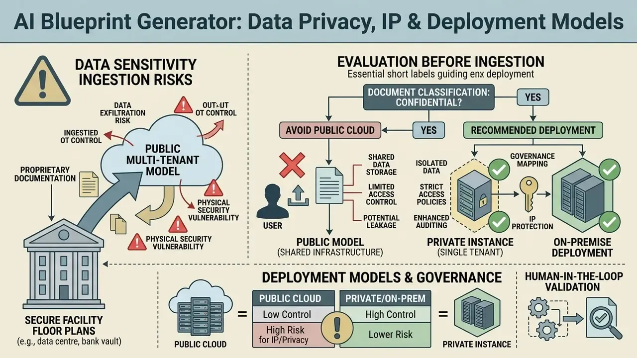
In two sentences: uploading proprietary floor plans of banks, data centres or secure facilities into a public multi-tenant model is a data-exfiltration and physical-security question, not just a procurement one. Assess deployment topology and retention terms before you assess capability.
Enterprise real estate documentation is often sensitive. Vault and secure-room locations, cash-handling paths, server-room adjacency, camera coverage, patient-care zones. Once that geometry leaves the perimeter, the exposure is not limited to intellectual property leakage. It becomes a facility-security disclosure, and those are not recoverable.
Evaluate any ai blueprint generator against the following before ingestion.
| Control area | What to require | Why it matters |
|---|---|---|
| Deployment topology | On-premise, VPC or private-cloud option; documented tenancy isolation | Prevents proprietary plans transiting shared inference infrastructure |
| Training-data use | Contractual guarantee that uploads are excluded from model training | Avoids inadvertent memorization of secure layouts |
| Retention and deletion | Defined retention window, verifiable deletion, export of audit logs | Supports records management and incident response |
| Certifications | Independent attestations (for example SOC 2 Type II, ISO/IEC 27001) and sector requirements where applicable | Evidence rather than assertion; verify scope and report date directly with the vendor |
| Access control | SSO, role-based access, per-project segregation | Limits internal over-exposure of sensitive schematics |
| Provenance and traceability | Content provenance metadata so each generated, modified or shared instance carries a tamper-evident history | Aligns with NIST digital-content-transparency recommendations |
| Model documentation | Records of fine-tuning, data augmentation and parameter changes | Required by the NIST Generative AI Profile for adapted pre-trained models |
Governance mapping matters as much as the controls themselves. Treat blueprint generation as a documented AI use case inside the existing model-risk inventory, assign a named owner, define escalation paths for erroneous output, and record the human review decision, including any override, consistent with human-review logging expectations. One caution: reference guides published by government bodies are frequently explicit non-binding operational references rather than policy. Your internal control set still has to do the work.
Best AI blueprint generator: how to choose the right tool
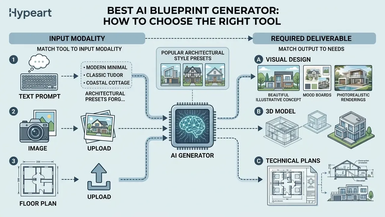
In two sentences: match the tool to your input modality first, then to the required deliverable. Everything else, styles, credits, interface polish, is secondary to whether the output can enter your production pipeline.
Selecting the best ai blueprint generator means comparing your organization's input formats against required output deliverables. Determine first whether the primary workflow runs on natural language prompting, hand-sketch vectorization or deep BIM integration. An ai blueprint creator optimized for concept imagery will disappoint a documentation team, and a BIM-grade pipeline is overkill for a marketing render.
Popular architectural style presets in AI generators
When prompting a blueprint maker ai, naming a defined architectural typology helps the model apply the right exterior massing, roof pitches and interior structural grids. Style-aware generators pair each typology with material combinations and layout principles learned from professional design corpora.
| Architectural style | Key structural characteristics | Recommended prompt constraints |
|---|---|---|
| Modern Farmhouse | Gable roofs, open-concept living, prominent front porch | 2-story, pitched roof, open floor plan, central kitchen island, wrap-around porch |
| Barndominium | Steel or post-frame shell, high ceilings, clear-span interiors | Post-frame shell, integrated workshop/garage, clear-span rectangular footprint |
| Ranch / single-level | Horizontal layout, low-pitch roof, segmented sleeping and living zones | Single-story, elongated footprint, attached 2-car garage, patio access |
| Tiny house / ADU | Compact footprint under 500 sq ft, vertical optimization, multi-functional spaces | Micro-layout, loft sleeping area, space-saving stair/ladder, wet bath layout |
| Cabin / lodge | Heavy timber or stick frame, steep roof for snow load, central hearth | Compact 1.5-story, steep gable, loft over great room, wood-burning hearth core |
| Small home / starter layout | Efficient circulation, minimal hallway area, stacked plumbing | 900 to 1,200 sq ft, 2 bed / 1 bath, stacked wet walls, no dedicated corridor |
| Contemporary flat-roof | Rectilinear massing, large glazing spans, cantilevers | Flat roof, floor-to-ceiling glazing on south elevation, cantilevered second story |
| Commercial branch / retail | Public-facing service zone, secure back-of-house, ADA restroom core | Single-story, entry queue zone, 4 service positions, secure storage without exterior wall |
Style presets improve plausibility, not compliance. Roof pitch and massing conventions are stylistic priors, whereas snow, wind and seismic loading remain engineering determinations.
Choose by input: text prompt, image or existing floor plans
Projects that begin with a client brief suit text-to-blueprint generators that digest plain-language space requirements. These engines shine when you need ten conceptual variations during an early programming meeting.
Renovation and adaptive reuse work needs the opposite: image-to-CAD generators that convert legacy paper prints, facade photographs or hand sketches into editable vector formats. A practical rule of thumb. Tools that advertise hand-drawn or sketch intake will trace and vectorize. Tools that advertise DWG or PDF intake will extract vectors and preserve layers. Document-parsing tools handle multi-page PDFs and structured field extraction, with page-count and file-size ceilings (PDF ingestion limits are documented at up to 50 MB or 1,000 pages, with per-page token costs). Watch for a frequent ambiguity: some vendors treat a PDF as an image, others as a document, and that single difference decides whether a scanned plan is usable at all.
For operational setup, consult the vendor's own configuration documentation rather than generic tutorials, because ingestion thresholds differ per engine.
Choose by output: visual design, 3D model or technical plans
If the objective is marketing visualization or fast client approval, 2D layout generators and lightweight 3D space planners are enough.
If the deliverable enters professional construction documentation, you need platforms supporting parametric BIM exports, layer-separated DWG files and strict structural line weight controls. The standards map helps here: ISO 128-1 covers 2D and 3D technical drawings, the 2003 edition explicitly excluded 3D CAD models (so verify which edition a vendor claims conformance with), and ISO 7519 governs construction drawings for general arrangement and assembly.
| Primary input modality | Desired output deliverable | Target use case | Recommended tool class |
|---|---|---|---|
| Natural language text | 2D conceptual floor plan | Feasibility and client ideation | LLM spatial layout engine |
| Hand sketch / scan | Vector DWG / DXF lines | Renovation and CAD migration | Computer vision vectorizer |
| Building photograph | Exploded orthographic PNG (plan, section, elevation) | Presentation and design review | Photo-to-orthographic diagram generator |
| Building footprint PDF | Code-aware space plan | Space allocation studies | Multi-conditional diffusion generator |
| Legacy plan archive (paper or PDF) | Structured, searchable building model | Portfolio digitization | OCR plus floor-plan parsing pipeline |
| Parametric BIM asset | 3D structural / MEP model | Construction and permitting | Generative AI-BIM pipeline |
AI blueprint generator FAQ
What is the difference between a floor plan and a blueprint?
A floor plan is one specific drawing type: a top-down view of a single level showing rooms, walls, doors and windows. "Blueprint" is a broader legacy term from the cyanotype reproduction process, and in common usage it now covers whole drawing sets, including floor plans, elevations, cross-sections, site plans, mechanical layouts and structural details. A complete construction set contains all of these. An AI generator typically produces a subset, which is exactly where expectations go wrong.
What building images work best for AI blueprint generation?
Highest accuracy comes from crisp, high-resolution, top-down orthogonal floor plan images or clean facade photographs shot in clear daylight. Source images should include visible dimension scale bars, minimal perspective distortion and clear contrast between structural walls and background space.
«Uploaded floor plans must be high enough resolution to read walls, doors and windows; a scale bar or readable dimension reference is required, and markings must not obscure detail.» Source: Archilogic ingestion requirements (2024). https://help.archilogic.com/ Documented practice elsewhere is stricter still. Approval-grade floor plans are required at no less than 1:100 scale, and facade documentation guidance specifies recent (within one month), colour, sharp, daylight photographs taken from two opposite sides and from the centre at roughly 40 to 50 m, capturing the facade with adjacent structures, with any projected element shown in orthographic projection to scale. Scans with heavy handwriting, complex watermarks or severe lens warp should be cleaned first. General photo-editing and enhancement workflows cover deskewing, contrast normalization and artifact removal before ingestion.
Can I customize styles, line weights and revisions after generation?
Yes. Professional AI blueprint platforms support post-generation customization: object line weights, drafting colors mapped to AIA plot style tables, room label edits, partition wall repositioning. Autodesk documentation confirms that lineweight is controllable in Plot and Page Setup, can be set as an object property, and can be customized through the Plot Style Table Editor, including plotted widths, line join and line end styles, while other CAD packages expose line weight directly in a toolbar for immediate editing. Advanced systems let users highlight a sub-region and re-run generative prompts locally without disturbing approved structural parameters elsewhere in the design.
«User evaluations of AI-generated floor plans show only moderate agreement on functionality and spatial organization, underlining the need for iterative human refinement.» Source: Mostafavi et al., Floor Plan Generation and Human-AI Interplay (2024). https://doi.org/10.1016/j.autcon.2024.105610
Can these outputs be used for construction or permits?
No. Vendor documentation across this category states plainly that generated blueprints are visualization, presentation and feasibility instruments. Actual construction requires detailed documents prepared by licensed architects and engineers, and permits require a stamp and signature from a current licensee in the governing jurisdiction. Photo-derived outputs carry an extra limitation: the model cannot see concealed structural elements and cannot produce precise measurements without reference data.
Is an AI blueprint generator suitable for beginners?
For concept work, yes. No drafting experience is needed. Describing a project in plain language ("a two-bedroom apartment with an open kitchen") yields a structured layout you can refine conversationally. What beginners cannot do is judge whether the result is buildable, which is precisely why the validation checklist above and licensed review exist.
What export formats should I expect?
Concept tiers usually deliver PNG or JPG. Production tiers deliver PDF, DWG, DXF, IFC and frequently STEP, FBX, OBJ, DGN or DWF/DWFX. Handover-oriented workflows add COBie tabular data, and urban-scale contexts add CityGML. Some presentation-focused tools output high-resolution PNG only, with 3D shown as a non-exportable render, so verify format support before assuming CAD interoperability.
How many credits does a generation cost?
It varies by vendor and model tier. Documented examples include 4 to 6 credits per blueprint generation against a 12-credit starter allowance, 10 design credits per week on one free tier, and monthly credit pools around 100 on adjacent 3D tools. Higher-fidelity models and larger texture resolutions burn more credits per run.
Appendix A, revision notes
Date corrections applied. Earlier drafts of this guide cited an engineering AI guidance memorandum and an RLVR spatial-research preprint with publication years that could not be independently confirmed, plus a copyright position dated inconsistently as "2024/2025." Agency guidance in this space is revised on a rolling basis. The current text cites the editions in force and instructs readers to verify the version applicable to their project. Where a preprint date could not be confirmed, the citation is presented as a preprint rather than as settled literature.
Off-topic anchors removed. Three outbound anchors in earlier drafts pointed to consumer video utilities and unconstrained text generation, which have nothing to do with CAD or BIM ingestion. They were replaced by raster-to-vector preprocessing guidance, CAD-oriented image cleanup discussion and prompt-constraint engineering, the topically correct upstream steps for architectural parsing. Navigational anchors ("view the guide", "open the hub", "browse the hub", "compare options", "explore the hub") were rewritten as descriptive anchors.
Unverified claims flagged. Two practitioner scenarios, the archive digitization throughput and the 80-hour drafting saving, are retained as practitioner estimates and explicitly marked as unaudited. Free-tier credit figures are presented as vendor-specific ranges rather than a market standard, because published values differ by credit unit and reset cycle. Vendor accuracy percentages (80%, then 90 to 95%) are noted as non-comparable across sources, because the underlying metrics differ: schematic-room-layout scoring, IoU spatial accuracy, internal parsing accuracy.
Expert attribution. The quotation is attributed to Marcus Hale, author.